

- Joined
- Dec 17, 2012
- Messages
- 39
- Points
- 0
Hey guys,
Recently I was advised in perchasing this W200 /RGB200mW by the comunity during a thread i started asking questions about a project i wanted to build.
Since then the Item has arived in super fast shipping, and I thought id make a little review and a tuturial also on how to controll it with a simple Arduino Microcontroller that you can pick up realy cheap.
Here I will be posting 2 controll methods, code and schematics.
________________________________________________
W200 /RGB200mW
SPECS (as reported by Shenzhen Optlaser Technology Co., LTD )

This little thing is heavy! It has a fun inside to keep it cool and as of far i havnt notices the unit heat up.
As you see the unit has to adjustment screws on the front the align the two mirrors inside on 1 axis,
the seccond axis is controlled by the screws on the side.

When mine arived it was only every sooo slightly out of alighment that with 5 meteres it is not noricable but after that you do see a little bit of colour seporation in the beam, with hint of red to one side and a hint of blue to the eother side with green in the middle.
I think this was due to the shipiing process as the mirrors would have goten nocked around a little whipe in transit.
I still have not gotten around to aligning it properly as im tooo scared i will only make it worse haha.
The PCB on the top, dose not show any signs of short cutts, "bodge wires" or slopy soldering.
It has 3 ports on the side that are for the PWM controll for each laser. The pins are labeld clearly wish silkscreen on the pcb.
There is another plug socket for 12V DC and a mistirois 3rd plug on the right wich i have no idea what it dose.
If some one knows it would be awsome!! I applyed 12v dc to that plugtop and a red laser shun, and i was to scared to burn it out and imediatly disconecetd it.

mystery plug with no silkscreen labling.

Over all great laser for its price, and the beam is as close to white as youll get for this price rang (almost perfectly white, althowe beam always looks blue on my iphone -_- )
Heres the tuurial part.
________________________________________________
For Ideviual colour controll
This uses 1 pot to scroll threw the brightness and a single button to change wich diode you have selected.
How to wire it.
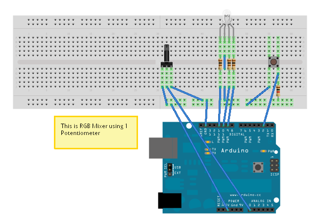
Ofcorse instead of wiring it to the LED, you wire it to you wire each one to the +'s of each colour.
the -'s all conect to gether to nurtual.
________________________________________________
The seccond method
This method will have the diode slowly fade between all the colours, and even mixing other colours in to such as purple pink, aqua, ad so on.
For this method, You simple conect Red to pin 11, Green to pin 10, Blue to pin 9, Cathodes to GND.
Heres a video of this method. (mind you colours do not come out right due to iphone)

________________________________________________
I hope you guys have found this helpful/imformative and educational.
If you would like to recognise the time and effort put into this posting please feel free to give me a little rep")
________________________________________________
________________________________________________
________________________________________________
________________________________________________
Recently I was advised in perchasing this W200 /RGB200mW by the comunity during a thread i started asking questions about a project i wanted to build.
Since then the Item has arived in super fast shipping, and I thought id make a little review and a tuturial also on how to controll it with a simple Arduino Microcontroller that you can pick up realy cheap.
Here I will be posting 2 controll methods, code and schematics.
________________________________________________
W200 /RGB200mW
SPECS (as reported by Shenzhen Optlaser Technology Co., LTD )
- Red 650nm/100mW
- Green 532nm/30mW
- Blue 470 nm/80mW
This little thing is heavy! It has a fun inside to keep it cool and as of far i havnt notices the unit heat up.
As you see the unit has to adjustment screws on the front the align the two mirrors inside on 1 axis,
the seccond axis is controlled by the screws on the side.
When mine arived it was only every sooo slightly out of alighment that with 5 meteres it is not noricable but after that you do see a little bit of colour seporation in the beam, with hint of red to one side and a hint of blue to the eother side with green in the middle.
I think this was due to the shipiing process as the mirrors would have goten nocked around a little whipe in transit.
I still have not gotten around to aligning it properly as im tooo scared i will only make it worse haha.
The PCB on the top, dose not show any signs of short cutts, "bodge wires" or slopy soldering.
It has 3 ports on the side that are for the PWM controll for each laser. The pins are labeld clearly wish silkscreen on the pcb.
There is another plug socket for 12V DC and a mistirois 3rd plug on the right wich i have no idea what it dose.
If some one knows it would be awsome!! I applyed 12v dc to that plugtop and a red laser shun, and i was to scared to burn it out and imediatly disconecetd it.
mystery plug with no silkscreen labling.
Over all great laser for its price, and the beam is as close to white as youll get for this price rang (almost perfectly white, althowe beam always looks blue on my iphone -_- )
Heres the tuurial part.
________________________________________________
For Ideviual colour controll
This uses 1 pot to scroll threw the brightness and a single button to change wich diode you have selected.
How to wire it.
Ofcorse instead of wiring it to the LED, you wire it to you wire each one to the +'s of each colour.
the -'s all conect to gether to nurtual.
Code:
int brightness = 0;
int potPin = A0;
int switchPin = 2;
int blue = 11;
int green = 10;
int red = 9;
int val;
int val2;
int switchValue;
int mode = 0;
void setup() {

  pinMode(blue, OUTPUT);
  pinMode(green, OUTPUT);
  pinMode(red, OUTPUT);
  pinMode(switchPin, INPUT);

  switchValue = digitalRead(switchPin);

}
void loop() {
   val = digitalRead(switchPin);
  delay(10);
  val2 = digitalRead(switchPin);
  if (val == val2) {
    if (val != switchValue) {
      if (val == LOW) {
        if (mode == 0) {
          mode = 1;
        } else {
          if (mode == 1) {
            mode = 2;
            } else {
            if (mode == 2) {
                mode = 0;
              }
   }
          }
        }
      }
    }
    switchValue = val;

  brightness = analogRead(potPin);
  if (mode == 0) {
  analogWrite(red, brightness / 4);
   }

  if (mode == 1) {
  analogWrite(green, brightness / 4);
   }

  if (mode == 2) {
  analogWrite(blue, brightness / 4);
   }

}
________________________________________________
The seccond method
This method will have the diode slowly fade between all the colours, and even mixing other colours in to such as purple pink, aqua, ad so on.
For this method, You simple conect Red to pin 11, Green to pin 10, Blue to pin 9, Cathodes to GND.
Heres a video of this method. (mind you colours do not come out right due to iphone)
Code:
/*
  Fade RGB LED Smoothly through 4 colours
  Fades an RGB LED using PWM smoothly through 4 different colours pausing for 1.5 seconds on each colour.

  Connect an common Cathode RGB LED with appropriate resistors on each anode to your Arduino Uno;
  Red to pin 11, Green to pin 10, Blue to pin 9, Cathode to GND.

  Developed for Arduino Uno by Joshua David - TechHelpBlog.com

  Please Feel Free to adapt and use this code in your projects.
 Contact me at techhelpblog.com and let me know how you've used it!
 */

// Assign LED Output PWM Pins
int Red = 11;
int Green = 10;
int Blue = 9;

//Set Initial Values
int RedVal = 0;
int GreenVal = 0;
int BlueVal = 0;
int fade = 10;  // Delay Time

// Colour Value 1 as each colour intensity (0-255)
int RedVal1 = 186;
int GreenVal1 = 0;
int BlueVal1 = 255;

// Colour Value 2
int RedVal2 = 9;
int GreenVal2 = 239;
int BlueVal2 = 26;

//Colour Value 3
int RedVal3 = 255;
int GreenVal3 = 120;
int BlueVal3 = 0;

//Colour Value 4
int RedVal4 = 0;
int GreenVal4 = 255;
int BlueVal4 = 78;

//Set initial mode (Colour Value Mode) to Colour Value 1
int mode = 1;

void setup()
{

 //----------------------- Assign outputs
   pinMode(Red, OUTPUT);
   pinMode(Green, OUTPUT);
   pinMode(Blue, OUTPUT);
 //----------------------- Write Initial Values of 0 to outputs
   analogWrite(Red, RedVal);
   analogWrite(Green, GreenVal);
   analogWrite(Blue, BlueVal);

}

void loop()                            // Begin Main Program Loop

{
  while(mode == 1){
    if(RedVal < RedVal1){              // If RedVal is less than desired RedVal1
      RedVal ++;                       // increment RedVal
    } else if(RedVal > RedVal1){       // If RedVal is more than desired RedVal1
      RedVal --;                       // decrement RedVal
    } else if(RedVal == RedVal1){      // If RedVal is equal to desired RedVal1
      //Do Nothing
    }
                                       // Repeated as above for BlueVal
    if(BlueVal < BlueVal1){
      BlueVal ++;
    } else if(BlueVal > BlueVal1){
      BlueVal --;
    } else if(BlueVal == BlueVal1){
      //Do Nothing
    }
                                       // Repeated as above for GreenVal
    if(GreenVal < GreenVal1){
      GreenVal ++;
    } else if (GreenVal > GreenVal1){
      GreenVal --;
    } else if (GreenVal == GreenVal1){
      // Do Nothing
    }
                                       // Now we have a new set of values, we write them to the PWM Pins.
    analogWrite(Red, RedVal);
    analogWrite(Green, GreenVal);
    analogWrite(Blue, BlueVal);
    delay(fade);                       // Implement a bit of delay to slow the change of colour down a bit

    if(RedVal == RedVal1 && GreenVal == GreenVal1 && BlueVal == BlueVal1){ // If RedVal & GreenVal & BlueVal are all at the desired values
      delay(1500);                     // Delay to hold this colour for a little while
      mode = 2;                        // Change the mode to the next colour. Exiting this while loop and into the next one
    }
  }

  while(mode == 2){
    if(RedVal < RedVal2){
      RedVal ++;
    } else if(RedVal > RedVal2){
      RedVal --;
    } else if(RedVal == RedVal2){
      //Do Nothing
    }

    if(BlueVal < BlueVal2){
      BlueVal ++;
    } else if(BlueVal > BlueVal2){
      BlueVal --;
    } else if(BlueVal == BlueVal2){
      //Do Nothing
    }

    if(GreenVal < GreenVal2){
      GreenVal ++;
    } else if (GreenVal > GreenVal2){
      GreenVal --;
    } else if (GreenVal == GreenVal2){
      // Do Nothing
    }

    analogWrite(Red, RedVal);
    analogWrite(Green, GreenVal);
    analogWrite(Blue, BlueVal);
    delay(fade);

    if(RedVal == RedVal2 && GreenVal == GreenVal2 && BlueVal == BlueVal2){
      delay(1500);
      mode = 3;
     //break;
    }
  }

  while(mode == 3){
    if(RedVal < RedVal3){
      RedVal ++;
    } else if(RedVal > RedVal3){
      RedVal --;
    } else if(RedVal == RedVal3){
      //Do Nothing
    }

    if(BlueVal < BlueVal3){
      BlueVal ++;
    } else if(BlueVal > BlueVal3){
      BlueVal --;
    } else if(BlueVal == BlueVal3){
      //Do Nothing
    }

    if(GreenVal < GreenVal3){
      GreenVal ++;
    } else if (GreenVal > GreenVal3){
      GreenVal --;
    } else if (GreenVal == GreenVal3){
      // Do Nothing
    }

    analogWrite(Red, RedVal);
    analogWrite(Green, GreenVal);
    analogWrite(Blue, BlueVal);
    delay(fade);

    if(RedVal == RedVal3 && GreenVal == GreenVal3 && BlueVal == BlueVal3){
      delay(1500);
      mode = 4;
      //break;
    }
  }

  while(mode == 4){
    if(RedVal < RedVal4){
      RedVal ++;
    } else if(RedVal > RedVal4){
      RedVal --;
    } else if(RedVal == RedVal4){
      //Do Nothing
    }

    if(BlueVal < BlueVal4){
      BlueVal ++;
    } else if(BlueVal > BlueVal4){
      BlueVal --;
    } else if(BlueVal == BlueVal4){
      //Do Nothing
    }

    if(GreenVal < GreenVal4){
      GreenVal ++;
    } else if (GreenVal > GreenVal4){
      GreenVal --;
    } else if (GreenVal == GreenVal4){
      // Do Nothing
    }

    analogWrite(Red, RedVal);
    analogWrite(Green, GreenVal);
    analogWrite(Blue, BlueVal);
    delay(fade);

    if(RedVal == RedVal4 && GreenVal == GreenVal4 && BlueVal == BlueVal4){
      delay(1500);
      mode = 1;                                 // Set mode back to 1 to return to the original colour.
      //break;
    }
  }

}
________________________________________________
I hope you guys have found this helpful/imformative and educational.
If you would like to recognise the time and effort put into this posting please feel free to give me a little rep
________________________________________________
________________________________________________
________________________________________________
________________________________________________


 your soft gave me some good ideas, lets see how can I make mine work..