Subject - G&P 467A chinese airsoft red lasersight
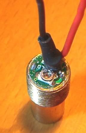
Red wire is +3.27v from the main circuit board.
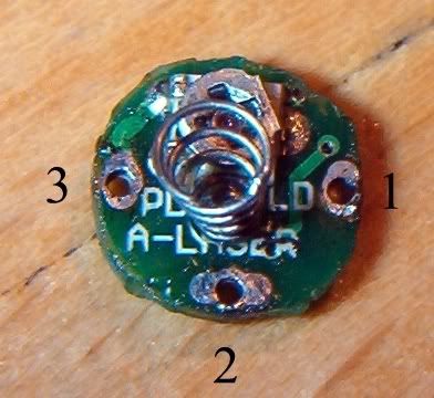
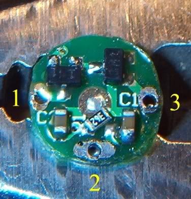
I pried up the little diode board to look under it. The diode has 3 pins, all sticking up through solder points on the edge of the board.
The red wire connects to Pin 2, which is also common with the case. That pin is labeled "A-LASER" on the board. I assume that means "Anode-Laser"??
All tests below were performed with the laser on.
Current through the red supply wire is 59mA. Current does not change when the pot is turned.
In the picture, the pin to the "right" of the pot is labeled "PD". With the red DMM lead on Pin 2 and the black lead on the PD pin, I get a variable voltage of +2.94 to +3.27v, depending on pot setting.
In the picture, the pin to the "left" of the pot is labeled "LD". With the red lead on Pin 2 and the black lead on the LD pin, I get a fixed voltage of +2.35, regardless of pot setting.
So it appears that the pot is causing variable voltage on the leg that is labeled PD.
Is that how it is supposed to work? Is this thing labeled correctly?
I guess I had assumed that the variable voltage would be on the LD leg, not the PD leg.
I'm assuming that this must be an N-type diode because the power supply is into Pin 2, making Pin 2 the LD Anode, and N-type is the only type where Pin 2 is the LD anode??
So. Am I on the right track, or totally derailed? ;D
Red wire is +3.27v from the main circuit board.
I pried up the little diode board to look under it. The diode has 3 pins, all sticking up through solder points on the edge of the board.
The red wire connects to Pin 2, which is also common with the case. That pin is labeled "A-LASER" on the board. I assume that means "Anode-Laser"??
All tests below were performed with the laser on.
Current through the red supply wire is 59mA. Current does not change when the pot is turned.
In the picture, the pin to the "right" of the pot is labeled "PD". With the red DMM lead on Pin 2 and the black lead on the PD pin, I get a variable voltage of +2.94 to +3.27v, depending on pot setting.
In the picture, the pin to the "left" of the pot is labeled "LD". With the red lead on Pin 2 and the black lead on the LD pin, I get a fixed voltage of +2.35, regardless of pot setting.
So it appears that the pot is causing variable voltage on the leg that is labeled PD.
Is that how it is supposed to work? Is this thing labeled correctly?
I guess I had assumed that the variable voltage would be on the LD leg, not the PD leg.
I'm assuming that this must be an N-type diode because the power supply is into Pin 2, making Pin 2 the LD Anode, and N-type is the only type where Pin 2 is the LD anode??
So. Am I on the right track, or totally derailed? ;D