Paulostool
Member
- Joined
- May 24, 2024
- Messages
- 50
- Points
- 18
I was having a hard time searching high Vf boost drivers in a compact circular size that would fit in a flashlight body.
At some point I was convinced that I would not find it ready to buy at the size I wanted, and after some tests with the TPS61500 boost controller I finally decided to learn a new skill and design my first real PCB.
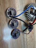
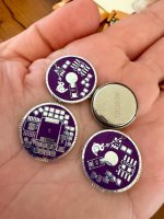
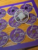
This is how Polyboost very slowly came to life over the last months!
Why Polyboost?
- it’s a 7135-less “Nanjg 105c” driver
- that instead of linear, it is a boost driver
- for lots of Vf (OVP at 25v, tested up to ~20v)
- fed by multiple LiPo cells
- with multiple analog dimming modes/levels (Open source FW’s compatible)
- built for multiple projects
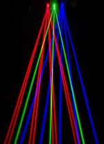
- all of them with multiple laser chips in series
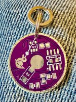
- and multipurpose: it’s also a keychain!
- and last but not least: contains a laser shooting bunny, that is also a duck
Very poly characteristics!
What it is not:
- not cool, this thing gets hot!
- not flawless, this is the first PCB design I sent for manufacturing and of course I made mistakes
- not protected against reverse polarity, I messed it up on the design. (Using a schottky for all the current was a simplistic dumb ideia)
- not my original circuit schematics, this project was heavily based on Giannis open source boost driver, TI reference for TPS61500 boost controller and Nanjg 105c schematics
- not a comercial product, I’m just a hobbyist filling all my free time with an obsession
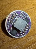
Main features:
- 22mm of diameter
- up to 4 Lipo cells (18v input)
- 2s slow start
- OVP set at 25v
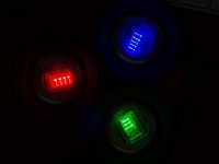
- Multiple modes: 1% to 100% analog dimming
- 1-mode jumper for no thinking, only full blast (MCU and LDO delete)
- Voltage monitoring and over discharge protection (Nanjg 105c FWs, needs appropriate voltage divider for the number of LiPo’s)
- Used FW: Biscuit.c from trebisky/Convoy repo on GitHub
- Tested configs:
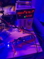
- Runs fine at 1A with ~7.4v input and ~17v output (~80% efficiency)
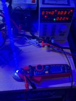
- Tested briefly at ~2A with 16.8V input and ~18V output
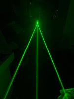
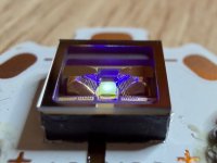
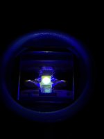
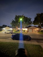
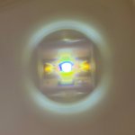
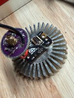
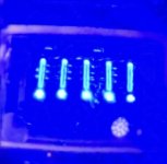
It works!
I’m very satisfied with the results, analog dimming works great up to ~1%!
It can shine the Qualas very gently
The extra planning on decoupling the “smart” and “power” sides was totally worth as I was able to test both things separately, always having the option of removing the MCU completely with a single jumper if it didn’t work.
Now it’s time to finish the first build using it!")
At some point I was convinced that I would not find it ready to buy at the size I wanted, and after some tests with the TPS61500 boost controller I finally decided to learn a new skill and design my first real PCB.
This is how Polyboost very slowly came to life over the last months!
Why Polyboost?
- it’s a 7135-less “Nanjg 105c” driver
- that instead of linear, it is a boost driver
- for lots of Vf (OVP at 25v, tested up to ~20v)
- fed by multiple LiPo cells
- with multiple analog dimming modes/levels (Open source FW’s compatible)
- built for multiple projects
- all of them with multiple laser chips in series
- and multipurpose: it’s also a keychain!
- and last but not least: contains a laser shooting bunny, that is also a duck
Very poly characteristics!
What it is not:
- not cool, this thing gets hot!
- not flawless, this is the first PCB design I sent for manufacturing and of course I made mistakes
- not protected against reverse polarity, I messed it up on the design. (Using a schottky for all the current was a simplistic dumb ideia)
- not my original circuit schematics, this project was heavily based on Giannis open source boost driver, TI reference for TPS61500 boost controller and Nanjg 105c schematics
- not a comercial product, I’m just a hobbyist filling all my free time with an obsession
Main features:
- 22mm of diameter
- up to 4 Lipo cells (18v input)
- 2s slow start
- OVP set at 25v
- Multiple modes: 1% to 100% analog dimming
- 1-mode jumper for no thinking, only full blast (MCU and LDO delete)
- Voltage monitoring and over discharge protection (Nanjg 105c FWs, needs appropriate voltage divider for the number of LiPo’s)
- Used FW: Biscuit.c from trebisky/Convoy repo on GitHub
- Tested configs:
- Runs fine at 1A with ~7.4v input and ~17v output (~80% efficiency)
- Tested briefly at ~2A with 16.8V input and ~18V output
It works!
I’m very satisfied with the results, analog dimming works great up to ~1%!
It can shine the Qualas very gently
The extra planning on decoupling the “smart” and “power” sides was totally worth as I was able to test both things separately, always having the option of removing the MCU completely with a single jumper if it didn’t work.
Now it’s time to finish the first build using it!
Attachments
-
 IMG_0864.jpeg461.9 KB · Views: 14
 -
 IMG_0865.jpeg334.5 KB · Views: 12
 -
 IMG_0923.jpeg539 KB · Views: 12
 -
 IMG_0920.jpeg468.9 KB · Views: 15
 -
 IMG_0873.jpeg647.8 KB · Views: 15
 -
 IMG_0982.jpeg295.1 KB · Views: 16
 -
 IMG_0994.jpeg284.9 KB · Views: 15
 -
 IMG_0984.jpeg195.3 KB · Views: 18
 -
 IMG_0996.jpeg447.4 KB · Views: 17
 -
 IMG_0997.jpeg38.9 KB · Views: 16
Last edited:


")