Welcome to Laser Pointer Forums - discuss green laser pointers, blue laser pointers, and all types of lasers

How to Register on LPF | LPF Donations

Need help with a laser

Laser_Spyro

New member
Joined
Feb 3, 2020
Messages
12
Points
3
Hi, I’m new to gas discharge lasers and found a few old boards in my community college. I was granted permission to see what I can do with them, and I am hoping to get them in working order using the original drivers. However, I have never seen this driver board before, and I saw a post made by a member about a laser with the same driver, but it was a different laser. The laser in this driver is a LGR 7655A, which I cannot find any data on at all. How do I power this specific board? Is this one straight 120v input, or am I underestimating the circumstances?
Thanks, I’d love to get these running again.
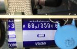
Also, I replaced the bad components and measured values as needed, everything looks to be in perfect order.465FB347-6CD6-47C0-A007-016BC136DA57.jpegFE6ACA27-FF8A-453A-8625-14FE9D97B2F9.jpeg4D6B8225-F33B-4B41-AA28-2E5B7A9631CD.jpeg


Hi, yes I see that your new here at LPF. OK first things first I see you didn't introduce yourself the WELCOME section .
So basically it a go home and do it again. We like folks to intro themselves , like to know little about you like from were your from , your likes of laser related builds etc..
maybe folks will be more willing to help you out.
Rich:)
Okay, I’ll go ahead and do that. Thanks mate.
 
I can't read anything. Please upload a picture with legible resolution. The underside may also be important.
 
I can't read anything. Please upload a picture with legible resolution. The underside may also be important.
Is this better? I can’t upload anything bigger because the site limits the file sizes far too much, and I’m forced to make the image smaller.
9987667E-B5FC-4B01-B3F4-6DAEEBFC99C8.jpeg
 
That tube is a 1 mW HeNe. It runs on about 1250 VDC at 4mA. It may or may not need an ignitor.

At first glance, that board looks like a DC powered supply... probably 12v at about 1 amp in. Just guessing, I would bet the transistor pulses the transformer and is then sent through multiplier circuit to achieve the 1250. The big resistors at the end are likely ballast for the tube to limit current.
 
Take a look at the voltage rating of the big electrolytic capacitor below the transformer on that board. If it's rated 160V or higher then it's a line powered driver. If its something like 25V then the driver runs off of 12V input.
 
Take a look at the voltage rating of the big electrolytic capacitor below the transformer on that board. If it's rated 160V or higher then it's a line powered driver. If its something like 25V then the driver runs off of 12V input.
So this is line powered, right?
Just want to make sure I don’t plug it in only to get a bright, loud *bang* and shards of projectiles in my body.
 

Attachments

  • 8C6E12D6-C72F-498E-A6A6-57A80651A909.jpeg
    8C6E12D6-C72F-498E-A6A6-57A80651A909.jpeg
    757.5 KB · Views: 2
Last edited:
That driver uses a line input. I can see the bridge rectifiers and the terminals marked as "A" and "B" are the AC input. Don't know right off what line voltage it was made for as it could be 110 VAC or 220 VAC. You still need to identify the anode and cathode connectors as they go to the tube. They are likely on the 6 pin plug labeled 101. Then again, there are two large resistors at the other end of the board and those could be the ballast.
 
That driver uses a line input. I can see the bridge rectifiers and the terminals marked as "A" and "B" are the AC input. Don't know right off what line voltage it was made for as it could be 110 VAC or 220 VAC. You still need to identify the anode and cathode connectors as they go to the tube. They are likely on the 6 pin plug labeled 101.
The tube is actually soldered in.
595B00A0-9BE2-417D-9407-B9926489E578.jpeg
Also, I found two marked pins on a connector (for inputs most likely) that look like they go to a switch or button that would activate the tube driver circuit via signal side
2CAE8A76-424E-450E-9F48-A2A412D940B4.jpegF2E440B4-B091-4366-9A02-BC491FD02E96.jpeg
 
Ah! There you go then. You could try 110 VAC. If it is 220 VAC then it might not start at 110. Stay away from the anode lead as it will bite you. The lead that goes to the two large resistors is likely the anode lead.

Are you talking about the pins marked as "C" and "D"? That could be a switch, IDK.
 
Last edited:
Okay, thanks! Just for reference, are these one shot or do they take a minute to warm up? I’ve only ever used LED lasers, so I’m used to one-shot activation.
 
If there is a delay it won't be more than a couple of seconds. I have some Siemens tubes with drivers and that is the longest delay any of them have. These are CW lasers.
 
Okay, thanks! Just for reference, are these one shot or do they take a minute to warm up? I’ve only ever used LED lasers, so I’m used to one-shot activation.
If the tube is tired it may flash or flicker on the way to lighting up. If it's very tired it may just flash a few times and quit trying.
 
Yeah, there is that. These tend to weather not being used for long periods of time well, though.


Back
Top