Paulostool
Member
- Joined
- May 24, 2024
- Messages
- 42
- Points
- 18
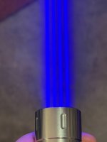
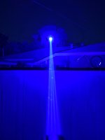
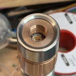
Another Qualas build, this time using a Nubb24t submodule.
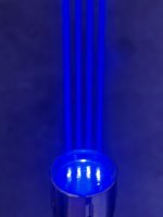
The Fan shaped beams were fun, but what about going parallel for this build?
Build summary:
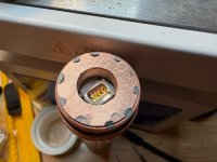
- Unsoldered the submodule from the Nichia module, I kept the original lens array this time
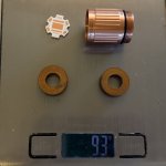
- Reflowed the 4 LD’s submodule in a 20mm DTP Copper board
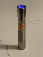
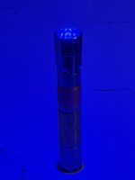
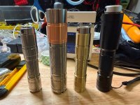
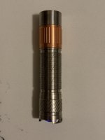
- Installed on a Convoy S21G copper head titanium body
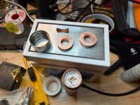
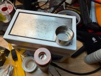
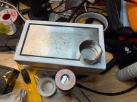
- Added a plastic ring for isolation followed by an 1/4” copper spacer, pressed with a copper shim + thermal compound
- Tapped another 1/4” slightly bigger cooper spacer with 11.5mm threads and fitted an glass window
- Bezel holds everything sandwiched together
For power I’m not using a Polyboost here, as the voltage needed was ~15.5v after warmup, I modified the Vout divider of the Convoy 12v 2.5a driver to make the MP3431 top at a theoretical 15.54v (right below its max 16v)
If the diodes are really cool, this just works as a CV driver until the Vf drops bellow the threshold, then it will regulate on CC mode at the 2.5a sensed by the shunt/op-amp.
I decided to not modify the current as this would put the booster IC way past its thermal rating.
The Fan shaped beams were fun, but what about going parallel for this build?
Build summary:
- Unsoldered the submodule from the Nichia module, I kept the original lens array this time
- Reflowed the 4 LD’s submodule in a 20mm DTP Copper board
- Installed on a Convoy S21G copper head titanium body
- Added a plastic ring for isolation followed by an 1/4” copper spacer, pressed with a copper shim + thermal compound
- Tapped another 1/4” slightly bigger cooper spacer with 11.5mm threads and fitted an glass window
- Bezel holds everything sandwiched together
For power I’m not using a Polyboost here, as the voltage needed was ~15.5v after warmup, I modified the Vout divider of the Convoy 12v 2.5a driver to make the MP3431 top at a theoretical 15.54v (right below its max 16v)
If the diodes are really cool, this just works as a CV driver until the Vf drops bellow the threshold, then it will regulate on CC mode at the 2.5a sensed by the shunt/op-amp.
I decided to not modify the current as this would put the booster IC way past its thermal rating.
Attachments
-
 IMG_1949.jpeg393 KB · Views: 5
 -
 IMG_1954.jpeg351.8 KB · Views: 6
 -
 IMG_1950.jpeg260.3 KB · Views: 5
 -
 IMG_1951.jpeg359 KB · Views: 5
 -
 IMG_1952.jpeg310.1 KB · Views: 5
 -
 IMG_1955.jpeg371.7 KB · Views: 4
 -
 IMG_1957.jpeg372.6 KB · Views: 5
 -
 IMG_1964.jpeg141.4 KB · Views: 5
 -
 IMG_2055.jpeg1.4 MB · Views: 6
 -
 IMG_2059.jpeg1.2 MB · Views: 5
Last edited: