Welcome to Laser Pointer Forums - discuss green laser pointers, blue laser pointers, and all types of lasers

LPF Donation via Stripe | LPF Donation - Other Methods

Links below open in new window

ArcticMyst Security by Avery

Maybe Third Time Is A Charm

Joined
Mar 4, 2014
Messages
139
Points
28
So I'm building a power supply for my red laser project and because this is the design that some of my students will build, I have to have everything just right. My first build was OK, but the PCB was a bit too small. The photo below shows the build without the heatsink on the LM317.

EDIT NOTE: I fixed the typo where I typed the wrong number.
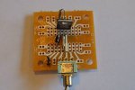
Power-1.JPG

I'm sorry that I don't have a shot with the heatsink, but it's a tight fit.

The second try is using a larger PCB, but I really didn't think out the layout very well and made a mess of it.
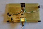
Power-2.JPG

Everything was looking great, UNTIL I added the heatsink:
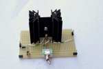
Power-3.JPG

Looking at it after the fact shows that I should have done a better job of picking the right spacing for things.

This project would have been finished, BUT because my electronics students might build it, I really should have things done correctly. Oh well, maybe the third time will work out...
 
Last edited:


Joined
Sep 12, 2007
Messages
9,399
Points
113
Forgive me for being blunt, but... you have students? As in, you're an electronics teacher? Where to start...

1) There's no need for two diodes - you have them both hooked up as reverse-polarity protection in different topologies.
2) Output capacitance is more important than input capacitance, yet you've omitted all output capacitance.
3) I have to assume you mean LM317, as the LM319 is a dual comparator in a DIP format.
4) It is hard to see the banding, but I think they're both 3.2Ω which sets the system at 390mA and 780mA with the switch open and closed, respectively. Is this your aim?
5) I hope you're aware the switch should NEVER be thrown while input power is applied, nor should the load be connected or disconnected while power is applied.
6) parasitic capacitance can present a hazard to sensitive electronics here. In addition to output capacitance, you should have a bleed resistor across the output to drain it.
7) 780mA is far too much for standard DVD lasers. What sort of laser diodes do you have in mind?
8) The PCB should be no larger than necessary. The first one was already plenty big, considering you only have one IC and a handfull of passives to solder.
9) Layout isn't all that important unless you've got space constraints, cost considerations, involving high speed, or involving high sensitivity.
10) If you do go for a fourth revision, in addition to incorporating some of the points above, I would recommend facing the back of the TO-220 away from the passives to make the heat sink easier to install. This also gives the option of folding it over to bolt onto something bigger instead of having a freestanding heat sink, should the need arise.
 
Last edited:
Joined
Mar 4, 2014
Messages
139
Points
28
Forgive me for being blunt, but... you have students? As in, you're an electronics teacher? Where to start...

1) There's no need for two diodes - you have them both hooked up as reverse-polarity protection in different topologies.
2) Output capacitance is more important than input capacitance, yet you've omitted all output capacitance.
3) I have to assume you mean LM317, as the LM319 is a dual comparator in a DIP format.
4) It is hard to see the banding, but I think they're both 3.2Ω which sets the system at 390mA and 780mA with the switch open and closed, respectively. Is this your aim?
5) I hope you're aware the switch should NEVER be thrown while input power is applied, nor should the load be connected or disconnected while power is applied.
6) parasitic capacitance can present a hazard to sensitive electronics here. In addition to output capacitance, you should have a bleed resistor across the output to drain it.
7) 780mA is far too much for standard DVD lasers. What sort of laser diodes do you have in mind?
8) The PCB should be no larger than necessary. The first one was already plenty big, considering you only have one IC and a handfull of passives to solder.
9) Layout isn't all that important unless you've got space constraints, cost considerations, involving high speed, or involving high sensitivity.
10) If you do go for a fourth revision, in addition to incorporating some of the points above, I would recommend facing the back of the TO-220 away from the passives to make the heat sink easier to install. This also gives the option of folding it over to bolt onto something bigger instead of having a freestanding heat sink, should the need arise.

(1) The second diode is my being paranoid about a reverse connection. I wanted to take any reverse voltage, with 0.05-10 uA of current, off of the key parts. Likely it doesn't matter, but better safe than sorry.
(2) I just took the design directly from the TI spec sheet, page 19:
LM317A.png
http://www.ti.com/lit/ds/symlink/lm317a.pdf
However, having capacitors at both ends is a good idea.
(3) Yes, that was a typo, I fixed the error.
(4) The first power supply (small PCB used 3.6 ohm resistors (measured 340mA & 680mA) and the second used 3.3 ohm resistors (measured 380mA & 750mA). Because of the small resistances in the connections, the current is always less than the calculations. Also, my 20A setting in the meter didn't allow me to read the single digit, so it's 38?mA & 75?mA. Final tests will be done at the school where I have better meters to use. The second is more in line about what I wanted.
(5) Yes, I power off between power setting changes.
(6) I forgot about that, but will add it.
(7) The maximum current for the diode (Mitsubishi 500mW 638 Diodes (ML501P73-02) ) is listed at 800mA. (DTR said 850mA.)
https://sites.google.com/site/dtrslasershop/home/diodes/mitsubishi-635nm-500mw-diodes
http://www.mitsubishielectric.com/s.../laserdevice/ldindis/638nm/ml501p73_p1245.pdf
(8) For me I like the small size, BUT I have to consider my students who have problems building things. I like to give them a little extra room to lay things out.
(9) I use the KISS concept for my students to avoid having them screw things up. That's why I go for an easy to see layout for their sake.
(10) The rotation of the heatsink was done to help the students see the pattern of input on the left to output on the right. If I had turned it around it would appear backward to them. They are NOT engineers, so I have to keep it simple for them. They are studying to be technicians.....

Each semester I get about 1 or 2 students that see my lasers and want to build one. I wanted a very simple design for them to build. We also are using Eagle Brand Laser Safety Glasses in class.
 
Joined
Sep 12, 2007
Messages
9,399
Points
113
I think you should give your pupils more credit, but I suppose you know them better than I. If you're insistent on a left-to-right flow, I suggest placing the TO-220 on the near edge, rather than the far edge.

Also, kudos for accepting input. Many others around here would opt for a tantrum instead.


Top